Welcome to Fulxing Intelligent - SMT Automation Equipment
 简体中文

Customer Service Hotline
18565526634
Welcome to Fulxing Intelligent - SMT Automation Equipment
18565526634
Contact: Mr. Yang
Mobile: 18565526634
Tel: 18565526634
Email: 1404870852@qq.com
Address: Songyu Rd 142, Songgang St, Bao'an Dist., Shenzhen, China
On a horizontal insertion machine, the quality metric of the lead-cutting station is the consistency of residual lead length. When lengths vary in production, the usual first response is to change the cutter. That only addresses one of two root causes. The other sits in the datum chain, where a new blade changes nothing.
Diagnosis requires two steps: establish a measurable acceptance criterion, then classify the error. With both done, the search narrows to one or two components.
The target residual length depends on board thickness and the downstream soldering process. The conventional window is 2.0 to 2.5 mm. This value governs solder rise during wave soldering: too short and vertical fill falls below the acceptance threshold, too long and bridging risk rises.
Consistency is judged on dispersion within a batch, not on any single reading. Take ten consecutive leads on the same row with an instrument of at least 0.02 mm resolution. The commonly used criterion is a range (R) not exceeding 0.15 mm. With n=10 and d2≈3.078, that corresponds to a standard deviation of roughly 0.049 mm, a level consistent with the repeatability of the cutting mechanism.
The measurement system has to be validated first. At 0.02 mm resolution, a caliper is already close to one tenth of the tolerance band, and operator pressure introduces additional variation. Where available, use a profile projector or vision measurement at 0.001 mm resolution. Measurement system variation should stay within 10 percent of the tolerance band; otherwise the "inconsistency" being investigated may originate in the gauge.
Random error shows up as follows: the same position on the same board, cut three times, produces three different lengths with no preferred direction. The sources are transient machine states, namely cutter wear, holder stiffness and drive repeatability.
Systematic error shows up as a regular offset across regions of one board, or a shift in the mean between boards. The sources lie in the datum chain: board flatness, locating pin coplanarity and base elevation.
Sample in two rounds. Round one repeats the same position three times and looks at the range. Round two takes one point at each corner and at the centre, and looks at the mean distribution. A large range in round one with a small spread in round two indicates random error; the reverse indicates systematic error. If both are large, address systematic error first, because it masks the random component.
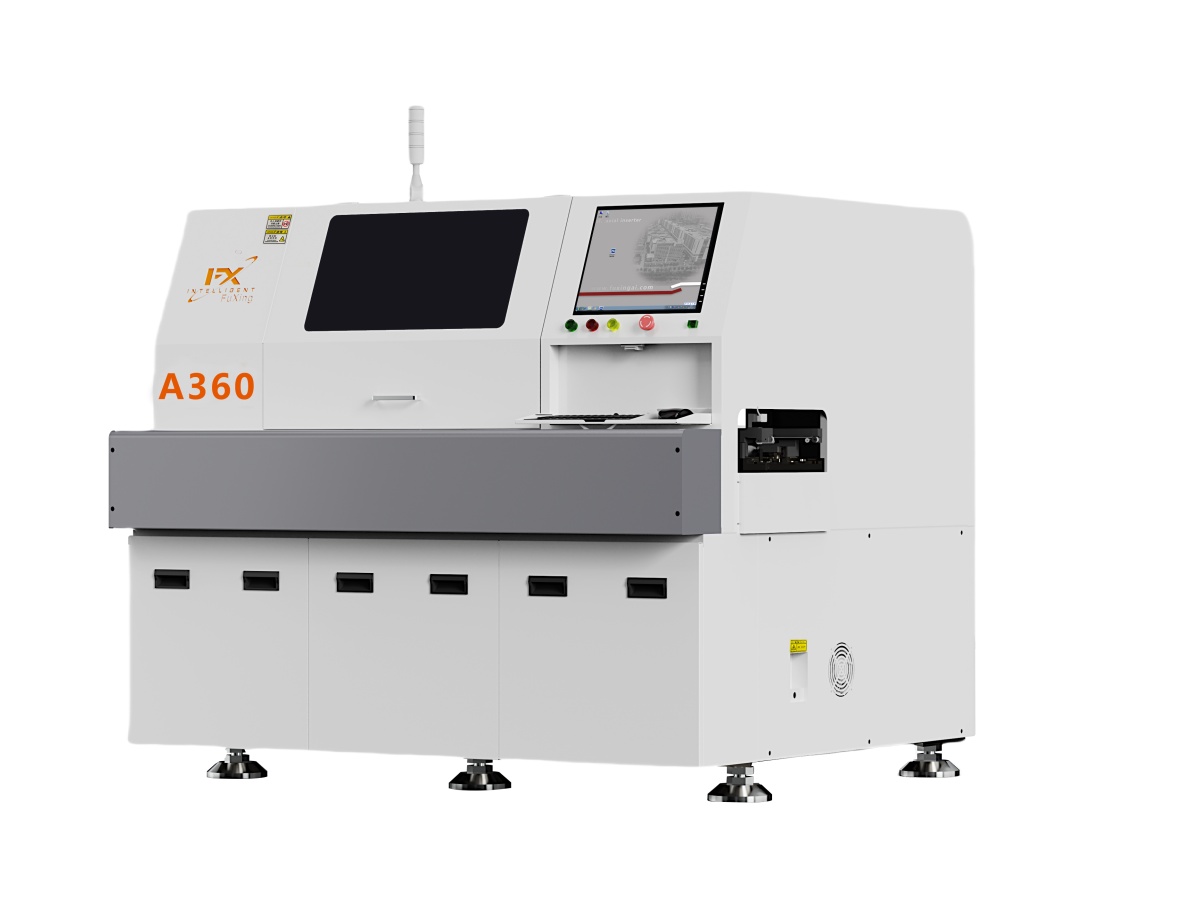
The cutting pair is the primary factor. Upper and lower blade clearance is normally set between 0.03 and 0.08 mm, checked with feeler gauges so the blade passes with light drag but does not rock. With excessive clearance the lead is bent rather than sheared, the cut face shows smearing and burrs, and length dispersion increases. With insufficient clearance the edges interfere and wear accelerates. A blade change is only valid if clearance is re-verified; mechanical installation alone does not constitute a proper replacement.
Holder and guideway stiffness is the second factor. Clamp screws lose preload over time, allowing micro-displacement of the cutter holder, which appears as dispersion increasing with running time. Guideway wear produces the same symptom, usually with audible noise. Both are maintenance items with low inspection cost and should be eliminated early.
Drive repeatability is the third. The cutting stroke is pneumatic, with the end position set by a magnetic sensor. Supply pressure fluctuation, debris in the exhaust throttle and seal ageing all shift the closing position. Air supply should be stable at 0.5 to 0.6 MPa; a fluctuation above 0.05 MPa makes stroke repeatability unattainable.
Board flatness comes first. Thin boards, large panels and boards that have already passed through one reflow cycle frequently exceed the permissible warpage. The cutting datum then follows the board surface, so residual length differs by region. Place the board on a surface plate and check corner clearance with a feeler gauge.
Locating pin and support pillar coplanarity is second. These two parts define the board datum; if either sits above or below the reference plane, the board tilts and the offset becomes a block pattern. Check with a dial indicator or by feeler gauge at multiple points.
Base elevation is third. Lift height directly changes the relationship between the shear plane and the board surface; insufficient parallelism produces a linear gradient across the board. The parameter has a specified value in the manual, and must be locked after adjustment, otherwise it drifts back within days.
Tool life should be tracked by cut count, not by calendar interval; batch differences make identical time spans correspond to very different wear.
Temperature rise is an independent accelerator. In continuous high-speed cutting, friction against tinned leads can raise blade surface temperature above 80 °C, at which point temper hardness falls and wear accelerates. An air nozzle aimed at the cutting zone cools the blade and clears chips at the same time. Water-based coolant is unsuitable: chips mixed with liquid promote abrasive wear and galvanic corrosion on the guideways.
Replacement should use a combined criterion: three consecutive cuts at the same position produce different lengths, and both clearance and concentricity have been verified, which indicates edge dulling. If length is stable but the mean is offset, the issue is the height parameter, and changing the blade will not help.
Residual length affects more than the insertion stage. It sets the exposed length available as the lead crosses the solder wave. Under the through-hole acceptance requirements of IPC-A-610, vertical fill is typically judged at 75 percent. Insufficient length prevents the fill requirement from being met; excessive length reduces spacing between adjacent leads, raises bridging risk and increases the moment applied to the board by the wave.
Burrs on the cut face are a separate concern. They retain flux and cleaning agents, acting as an ionic contamination source and reducing long-term reliability. Cut-face quality is directly tied to clearance and edge condition, which is why clearance verification cannot be skipped.
Q1: After fitting a new blade, dispersion is unchanged. Where else should I look?
Re-check blade clearance first. If the blade was installed without verifying the 0.03 to 0.08 mm window, the new blade may already be outside it. Next check the concentricity of the cutter head and the insertion head; an eccentric mounting shifts the edge relative to the lead. Once both are excluded, move to the datum side and check board flatness and locating pin coplanarity.
Q2: Dispersion grows after several hours of running and recovers after a stop. Why?
This is thermal drift. Edge temperature rise reduces hardness, while thermal expansion of the cylinder and guideways changes the fit. Confirm by stopping for ten minutes and resampling: if the first board is acceptable again, the cause is confirmed. Address it with forced air cooling, a lower continuous duty cycle, or by scheduling high-precision batches during the cold state.
Q3: Lead length is within tolerance but wave soldering shows low fill. Should the cutter be adjusted?
First confirm residual length is inside 2.0 to 2.5 mm and inspect the cut face for burrs. If both are acceptable, the problem lies in the soldering parameters: preheat profile, flux deposition and contact time. The cutting stage and the wave soldering stage are separate process windows, and adjusting the upstream parameter is not a valid compensation for a downstream defect.
Lead-cutting blades are consumables. Track replacement by cut count and keep one set of the same specification in spare parts stock. In workshops running many board types, assigning small boards to a vertical machine reduces the duty cycle on the horizontal machine's cutting pair and extends blade life measurably.





Copyright © 2002-2026 Shenzhen Fulxing Intelligent Equipment Co., Ltd. All rights reserved. ICP License:
Service Hotline