Welcome to Fulxing Intelligent - SMT Automation Equipment
 简体中文

Customer Service Hotline
18565526634
Welcome to Fulxing Intelligent - SMT Automation Equipment
18565526634
Contact: Mr. Yang
Mobile: 18565526634
Tel: 18565526634
Email: 1404870852@qq.com
Address: Songyu Rd 142, Songgang St, Bao'an Dist., Shenzhen, China
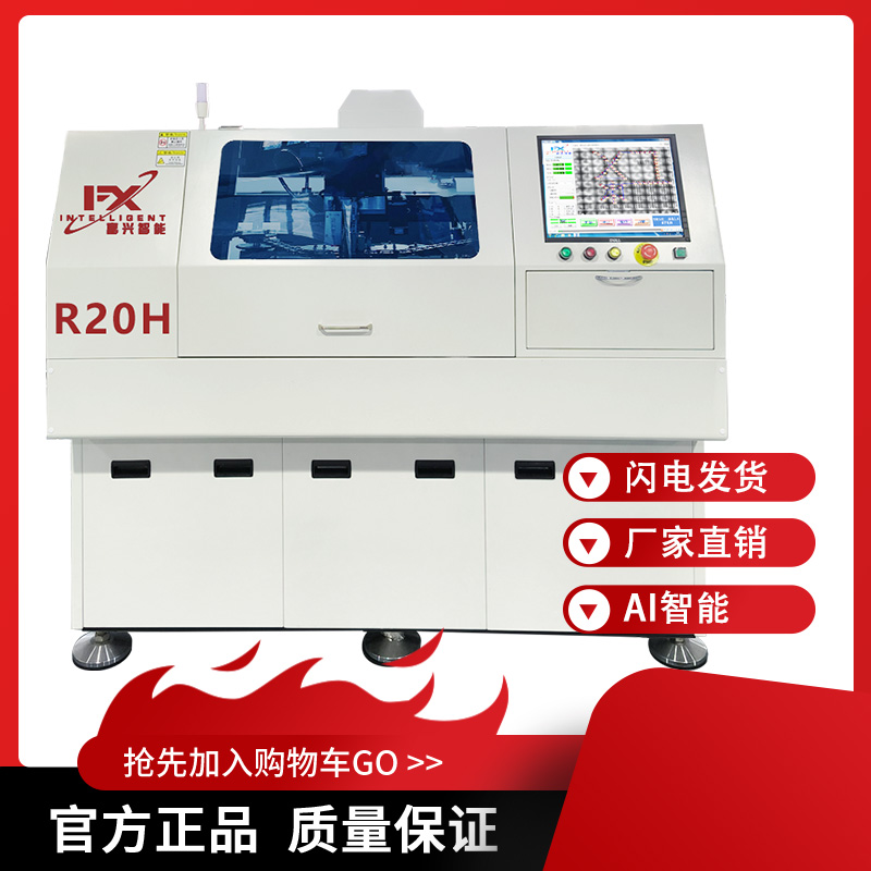
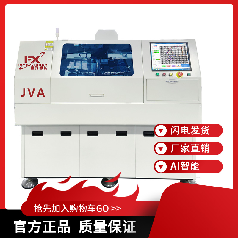
An automatic insertion machine does not solder. Its output state is: components seated, leads cut to specification, and no metallurgical bond between lead and barrel wall. Soldering is a separate stage performed by wave soldering or selective wave soldering. The two stages are adjacent in the process chain and entirely different in physical mechanism.
The confusion is widespread in industry content, usually phrased as "the insertion machine is typically equipped with wave or reflow soldering equipment." That sentence converts a line-level configuration into a single-machine function, and it misleads both selection and line planning. The chain is broken down below, stage by stage.
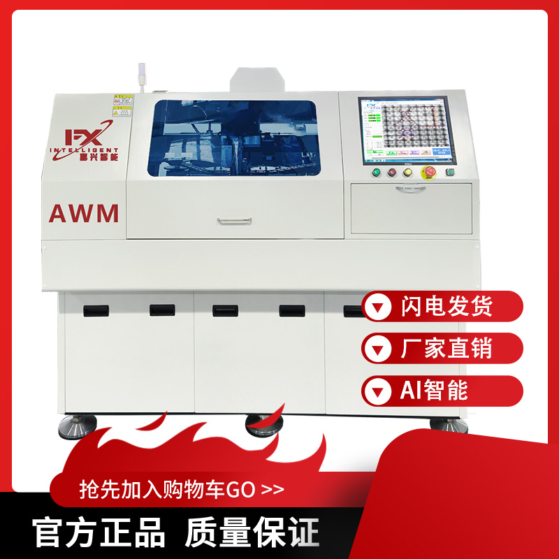
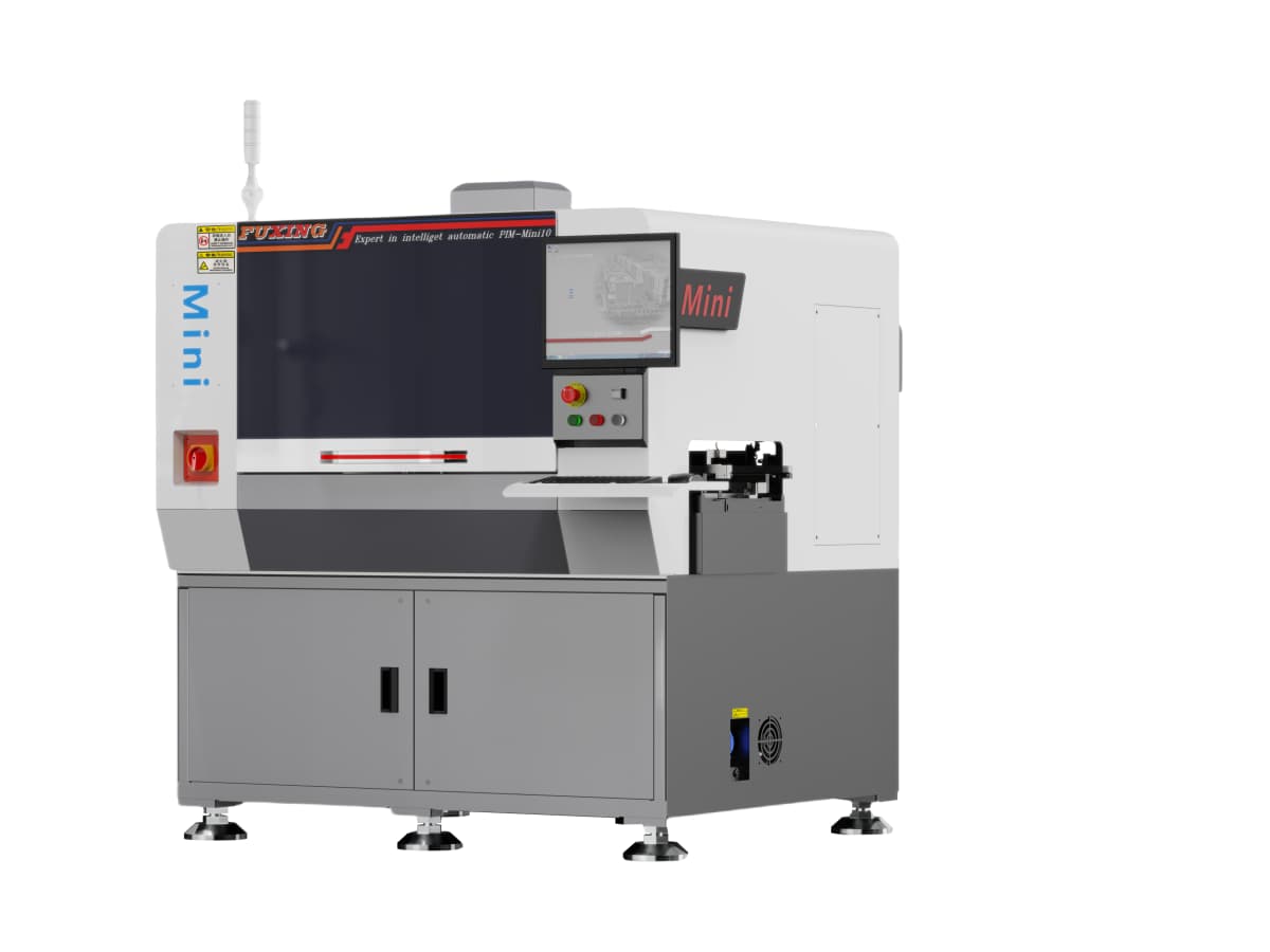
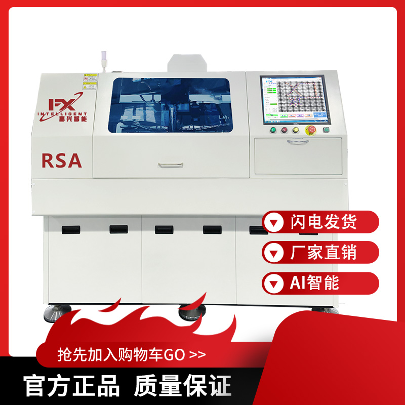
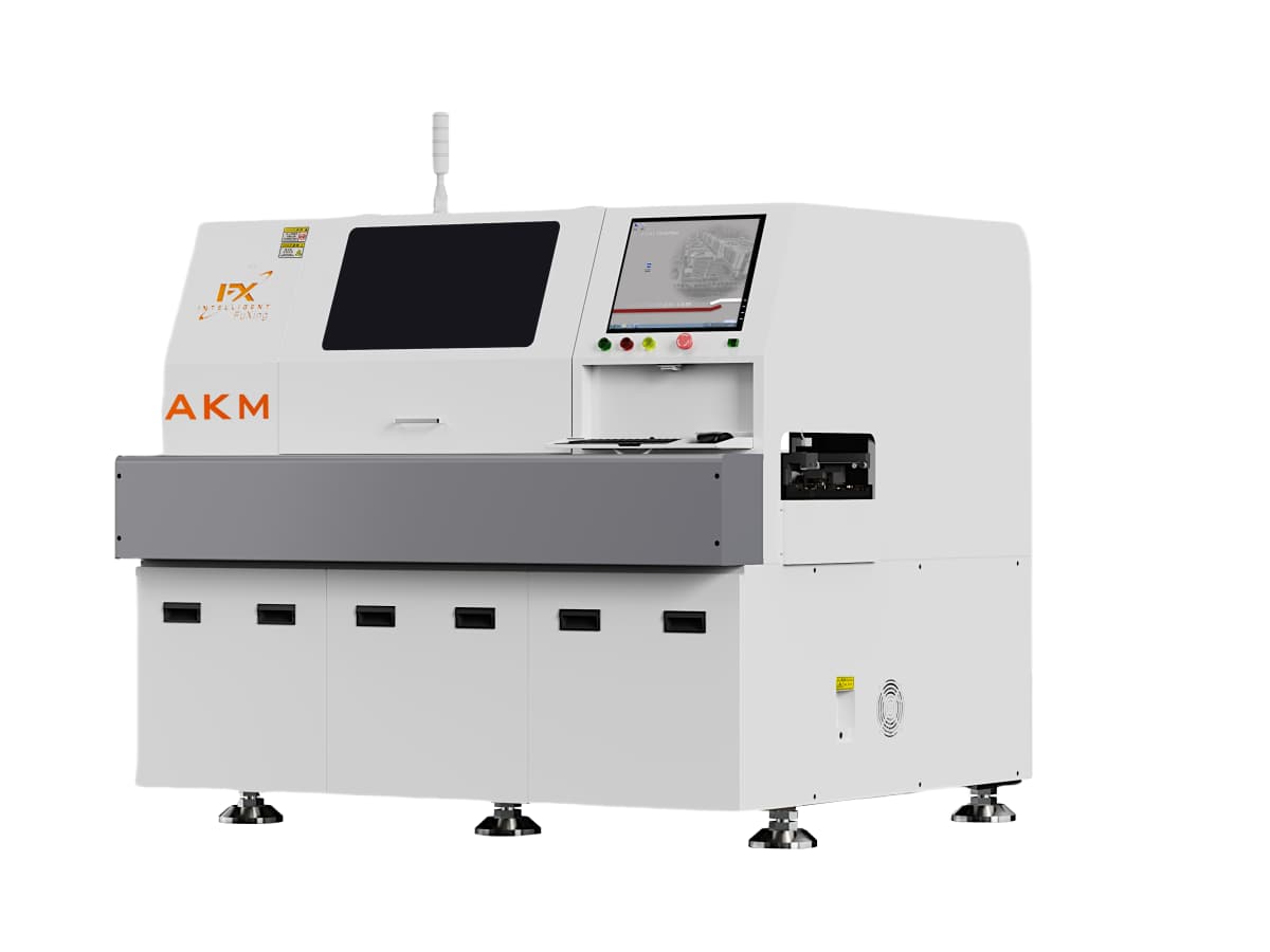
An insertion machine performs four actions within the DIP chain.
Feeding transfers components from packaging to the pick position. Formats include tape, tube, tray and vibratory bowl. For taped supply, stability depends on the feeder's step accuracy and peel force.
Insertion is carried out by a servo-driven head that positions and presses. Positioning accuracy is typically quoted at 0.01 mm, and machines rated at 0.16 to 0.2 seconds per point reach a nominal 20,000 points per hour. A spring compliance element and force monitoring limit damage to the barrel wall during pressing.
Lead cutting is optional. Machines fitted with a cutting mechanism shear the lead at the same station, with residual length set per process requirement. Machines without it need a standalone lead cutter downstream, or manual processing.
Detection covers missing components, reversed polarity, jams and feeding faults, using sensor signals and vision comparison.
After these four steps the component is mechanically located. There is no wetting between lead surface and barrel copper, and no intermetallic compound (IMC) has formed. The board has no electrical connection at this point.
Wave soldering proceeds as flux application, preheat, contact with the solder wave, and cooling. The pot is typically set near 260 °C, with contact time controlled in the range of seconds depending on board thickness and thermal mass. Flux removes oxide from lead and barrel, heat melts the alloy, capillary action draws it up the barrel, and an IMC layer forms on cooling, at which point the connection exists.
Products that cannot pass the whole board through the wave use selective wave soldering, with a program-controlled nozzle applying solder point by point. This applies where the board carries SMD parts, heat-sensitive connectors or already-soldered modules.
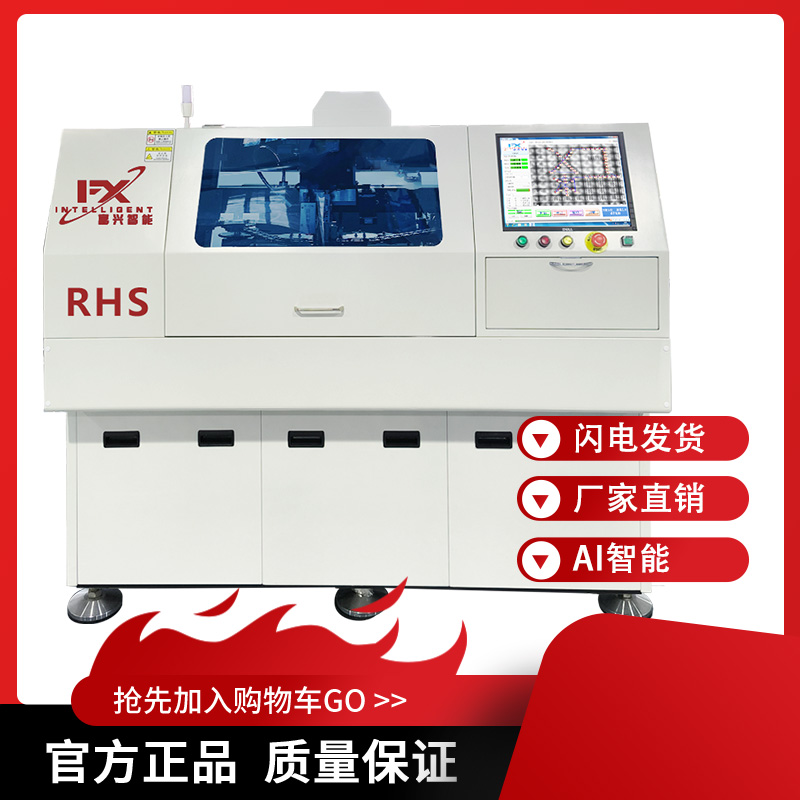
The obstacle is not mechanical structure but process nature.
Energy form differs. Insertion is a position and force control problem, with coordinate accuracy and press force as core variables. Soldering is a thermal and chemical process, with temperature profile, flux activity and wetting time as core variables. The control loops, sensing methods and failure criteria do not overlap.
Time scale differs. A single insertion is measured in tenths of a second; a board-level soldering pass is measured in tens of seconds and requires a stable thermal field that cannot start and stop with the insertion cycle.
Failure modes differ. Insertion defects are positional offsets, missing components, reversed polarity and lead damage; soldering defects are insufficient fill, bridging, voids and cold joints. Inspection methods, rework routes and responsibility boundaries follow that split.
Environment requirements differ. A solder pot must be held at temperature continuously, and flux volatiles are corrosive, which conflicts with the clean environment required by precision motion systems and vision hardware. Placing both in one enclosure raises sealing and protection cost substantially.
Equipment coordination relies on standardised interfaces. Board transfer in SMT and DIP sections commonly uses the SMEMA interface for handshake signals, including board present, board available and equipment ready, which prevents pile-ups and collisions. The technical agreement should specify the interface type and signal definitions; otherwise retrofitting is required after integration.
The conveyor buffer carries the buffering function. The inserter outputs boards intermittently while the wave feeds continuously; the difference is absorbed by buffer positions, typically two to three, and the count should match the magnitude of cycle variation.
Fixture (carrier) return is a logistics function. Carriers are configured at 1.2 times the work-in-process board count. Insufficient carriers make the inserter wait, producing downtime that has nothing to do with equipment capability. This item is frequently omitted in line planning, and its effect is comparable to a machine fault.
Plan in the order of fixing the soldering capacity first, then sizing the insertion section.
Wave capacity depends on conveyor speed and board length. At 1.2 m per minute, with 300 mm boards and 50 mm gaps, each board occupies 350 mm, giving about 3.4 boards per minute or roughly 200 per hour.
Inserter throughput must be derated by utilisation. At a nominal 20,000 points per hour and 70 percent utilisation, effective capacity is about 14,000 points per hour; a 200-point board corresponds to 70 boards per hour.
Dividing the two, one wave corresponds to approximately three insertion machines. At 300 points per board the ratio falls to about two. The ratio varies with product mix and must be calculated from the actual BOM rather than copied from a fixed configuration.
Machines that combine insertion with selective soldering do exist, with narrow applicability: few points per board, small batches, single product type, constrained board size. Cycle time, maintenance complexity and cost per unit of capacity are all higher than a split configuration, and such machines are not the mainstream solution for a production line.
Reading "automatic insertion machine" as a machine with soldering capability is a category error. The name refers to the degree of automation of the insertion action, and has nothing to do with the soldering stage.
Lead cutting: whether fitted, the permissible lead diameter range, the residual length range, and the method for judging cut-face quality.
Interface: standard adopted (for example SMEMA), signal definitions, transfer direction and track height. Track height must match the conveyor buffer and the wave; a deviation of a few millimetres requires shims and affects levelness.
Cycle time guarantee: state the test conditions, distinguish dry-cycle from actual-insertion time, and specify the test board point count and component types. The two can differ by a factor of two, and a guarantee that does not state the basis cannot be verified.
Acceptance method: sampling method and threshold for residual length, insertion position deviation, and the statistical definition of first-pass yield.
Q1: If we already have wave soldering, is any other equipment needed after adding an inserter?
It depends on the existing configuration. With a loader, conveyor buffer and wave already in place, adding the inserter and completing integration is usually sufficient. Where the board carries manually inserted components, their leads have not been machine-cut and the cutting operation must still be retained; where the inserter has no cutting function, a standalone cutter is required.
Q2: Can the machine's built-in cutter replace a standalone lead cutter?
Not entirely. Machine cutting only covers components placed by the machine. Manual insertions such as power devices, transformers and terminal blocks still need downstream processing. Whether a standalone cutter is justified depends on the manual point count and batch size.
Q3: Can vertical and horizontal machines share one wave soldering system?
Yes. The insertion section is configured by component type, while the soldering section is a shared resource, which makes it the capacity ceiling of the line. Calculate wave capacity first, then determine the number of insertion machines. Reversing the order produces excess insertion capacity and boards queuing in front of the wave.
Complete line configuration involves matching SMT peripheral equipment, and machine selection is covered by the component applicability of vertical and horizontal machines. The soldering stage does not change with the inserter model, which matters most when a line is expanded.

Copyright © 2002-2026 Shenzhen Fulxing Intelligent Equipment Co., Ltd. All rights reserved. ICP License:
Service Hotline