Welcome to Fulxing Intelligent - SMT Automation Equipment
 简体中文

Customer Service Hotline
18565526634
Welcome to Fulxing Intelligent - SMT Automation Equipment
18565526634
Contact: Mr. Yang
Mobile: 18565526634
Tel: 18565526634
Email: 1404870852@qq.com
Address: Songyu Rd 142, Songgang St, Bao'an Dist., Shenzhen, China
A range hood control board can contain a surprisingly mixed set of through-hole components. One design has rows of tape-fed resistors and capacitors; another is dominated by relays and connectors for the motor, lights and control panel. Calling both projects an “automatic insertion machine application” does not tell a buyer how many positions will actually be automated. Start with the bill of materials, not the board outline or a headline insertion speed.
List each through-hole reference designator alongside its approved part number, package drawing, incoming packaging, quantity per board and production volume. Mark surface-mount-only components separately; they do not belong in the insertion count. For each part, note whether it can be presented consistently to a feeder, whether its leads fit the finished PCB holes, and what the body looks like after insertion.
Tape-fed axial resistors or diodes may be candidates for a horizontal insertion machine. Some tape-fed radial capacitors, LEDs and similar leaded parts may suit a vertical insertion machine. “May” matters here. A change in lead span, body height, polarity orientation or tape format can require another feeder or forming tool, even if the component name remains the same. Evaluate an approved substitute as a separate line in the matrix rather than assuming it will run with the original setup.
Relays, terminal blocks, fuse holders and power connectors need an individual handling decision. Tube, tray, bulk and tape packaging present different pick-up problems. A part might be suitable for an odd-form insertion station with a dedicated gripper; another may be cheaper and safer to insert by hand at the planned volume. An axial tape-fed fuse is not equivalent, as an insertion task, to a rectangular fuse holder. This distinction is often lost when a quotation groups both under “fuses.”
The wiring harness has to reach the motor, lamp, mains input or user interface, so connector placement is often dictated by the enclosure. A connector that looks regular in a top-view PCB drawing may have locating pegs, latch features or an unusually tall housing. Gripping it is only half the test: the head must also clear parts already installed nearby and release the connector without pulling it back up.
Send the equipment supplier the actual housing envelope, peg positions, lead tips, insertion direction and a populated sample board. Verify access in the intended sequence, not on an empty PCB alone. Under-board support is equally important. If the board flexes beneath a connector, the machine can reach its programmed end position while the component remains above the intended seating height. Move a support pin carelessly, however, and it may obstruct a plated hole, a bottom-side component or the cut-and-clinch tooling. Support layout and insertion order should be demonstrated together in the trial.
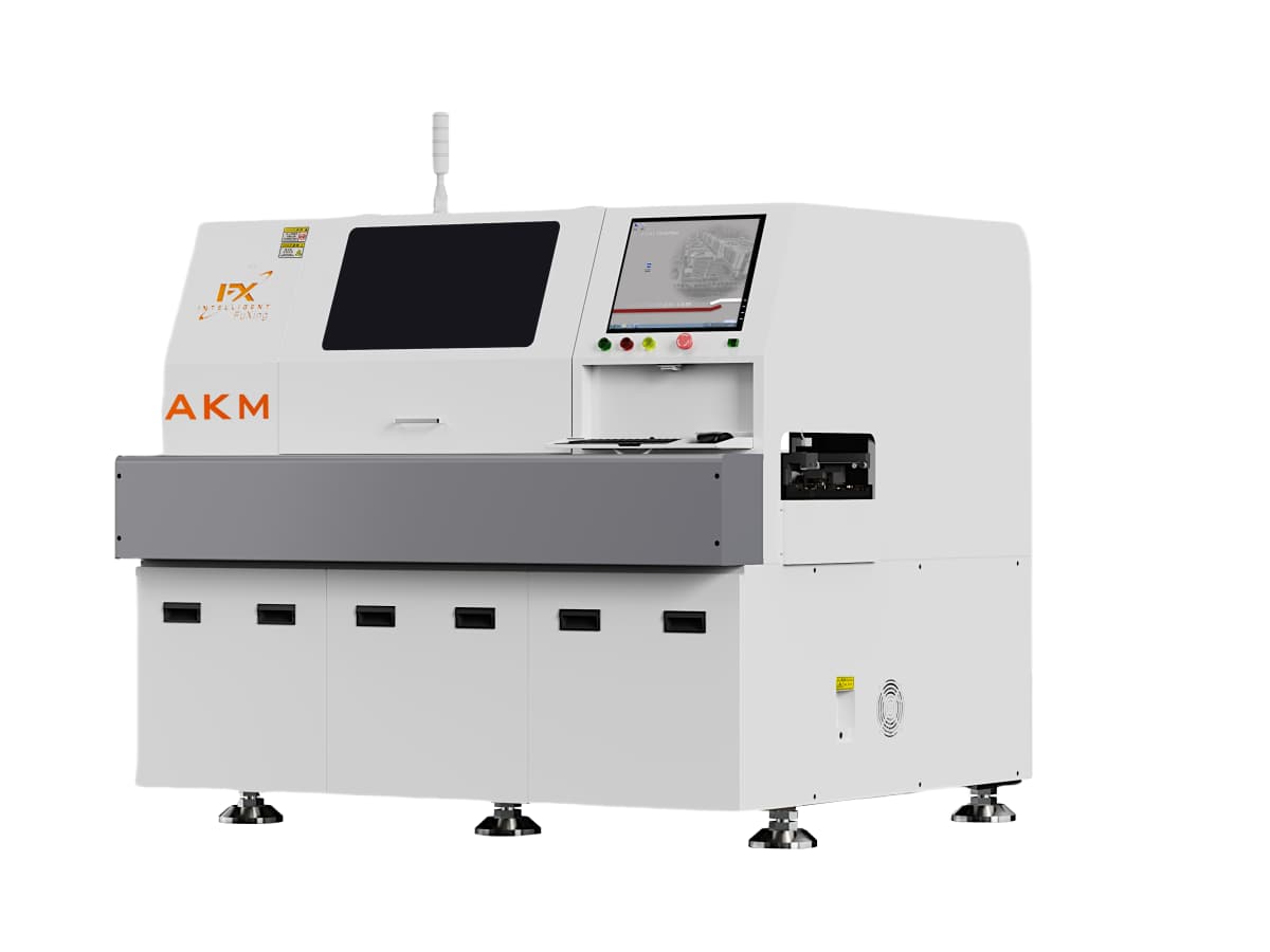
Consider three counts for every board revision: points reliably covered by standard axial or radial machines, points that an odd-form station can handle, and points still requiring manual insertion. If standard tape-fed components account for most of the stable workload, calculate the coverage and changeover requirements for standard machines first. If the board contains mostly connectors and relays, prove the gripping, feeding and hole fit of those parts before committing to a standard machine. A line that builds several low-volume hood models also needs an honest estimate of feeder changes, recipe selection and first-article checks.
Catalogue points-per-hour figures are not the same as good assembled boards per hour. Include replenishment, alarms, board transfers, model changes and the manual positions that remain. Compare the insertion section with the receiving capacity of the downstream wave soldering stage; there is little benefit in building a queue of half-finished boards ahead of soldering. In an RFQ, ask each supplier to show the part-level coverage they used to calculate capacity, rather than only a theoretical cycle time.
Do not qualify the machine with the neatest resistor reel alone. Include the tallest and heaviest parts, leads prone to bending, approved alternative suppliers, production PCBs and the actual panel and support fixture. Record the feeder, grip method, polarity, seated height, lead protrusion below the board and how an interruption is recovered. For odd-form parts, inspect lead scratches, body tilt and spring-back after release. Then take boards with their planned manual insertions through a pre-solder inspection to confirm the final assembly, not just an isolated machine action.
Put the result in the technical agreement at part-number level: which packaging runs directly, which requires an additional feeder or gripper, which parts remain manual, and what the acceptance sample and measurement method will be. A connector that repeatedly needs extra force is a reason to recheck finished hole dimensions, lead geometry and locating pegs—not a reason to keep increasing pressure until the alarm disappears.
Q1: Does every range hood board need axial, radial and odd-form machines?
No. The choice depends on the actual approved BOM, volumes and acceptable manual work. A few odd-form positions may not justify another machine, while a high-volume board with many tape-fed positions may.
Q2: Can a tape-packed relay automatically run on a radial inserter?
Not on packaging alone. Check the body envelope, lead geometry, feeder compatibility, insertion load and board clearance with the exact part in a trial.
Q3: What should we send with an insertion-machine RFQ?
Provide the PCB data, BOM and designators, component drawings and packaging, representative samples, production mix and downstream soldering process. Ask for a part-by-part automation and acceptance matrix in return.
For a range hood control board, the useful purchasing answer is a verified list of which part numbers the insertion equipment can place—and how many good boards the whole line can deliver—not a claim that one machine handles “home appliance PCBs.”

Copyright © 2002-2026 Shenzhen Fulxing Intelligent Equipment Co., Ltd. All rights reserved. ICP License:
Service Hotline