Welcome to Fulxing Intelligent - SMT Automation Equipment
 简体中文

Customer Service Hotline
18565526634
Welcome to Fulxing Intelligent - SMT Automation Equipment
18565526634
Contact: Mr. Yang
Mobile: 18565526634
Tel: 18565526634
Email: 1404870852@qq.com
Address: Songyu Rd 142, Songgang St, Bao'an Dist., Shenzhen, China
When a component sits high after automatic insertion, it is tempting to move the insertion head farther down. That can turn one visible defect into a damaged plated-through hole. First establish the intended stand-off height from the assembly drawing or approved first article: not every component is designed to sit flush against the PCB. Then take a board directly at the inserter exit, before soldering, and locate the step at which the height changed.
Measure the same reference designator at the machine exit and after soldering. Record the distance from the component body to a defined PCB surface, whether both ends are level, and how far each lead protrudes underneath. If the board exits the inserter with the component already high, investigate feeding, lead forming, finished holes, program settings and support. If the exit sample is correct but the component lifts after wave soldering, examine how the part is retained during transfer and in the soldering fixture. Increasing inserter pressure is not a remedy for a problem introduced later in the line.
The two board faces tell different stories. One protruding lead and one missing lead suggest a lead-span, shape or hole-entry problem. Similar protrusion on both sides with the whole body high is more consistent with a seating-depth or support issue—although an intentional body step must still be ruled out. If the part springs back after being pressed down, isolate the affected boards and look for interference or elastic lead deformation. Solder should not be used to freeze an unresolved mechanical load in place.
For axial and radial parts, incoming dimensions are only the starting point. The leads that actually approach the board may have passed through a forming or cutting tool. Compare an affected part taken from the feeder with an unprocessed part and a good formed sample. Measure the span and parallelism; inspect bend locations, body alignment and scratches in the lead finish. A defect limited to one tape lot or feeder station is a useful clue. Test an approved alternative batch before changing board-wide coordinates.
Leads spread too far can bind against the hole walls. An asymmetrical bend may let one lead enter while the other lands on a pad, lifting one side of the body. Compare the component drawing with the finished PCB hole, not just the drill callout, and check forming tooling and approved substitute parts. On an axial insertion machine, also confirm whether the drawing specifies a deliberate stand-off. A visible gap is not by itself proof of a faulty insertion.
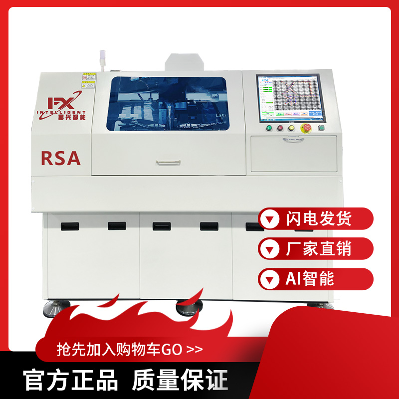
A Z-axis endpoint describes machine motion; it does not guarantee a particular distance between the released component and the board. If every instance of one part number is high, note the program revision and intended mounting height, then inspect pick-up orientation, where the insertion head holds the part and the Z reference. If only one area of the board is affected, pushing the head deeper for all placements may damage otherwise good holes and pads.
Change one variable at a time. Use the same board design and part lot, insert a first article after the adjustment, measure height on both sides and check lead protrusion below the board. Release the gripper and measure again. Stop if resistance rises unexpectedly or the board shows whitening, lifted pads or bent leads. Machines differ in force control and stroke control, so use the product drawing and the particular equipment manual for target heights and alarm limits; there is no transferable “extra depth” setting.
A recurring high placement near the centre of a panel, with good parts near the edge, points toward local board deflection or panel warp. The head applies load at the hole, an unsupported PCB moves down with it, and the board springs back as the tooling retracts. Verify that support is close to the loaded area and does not collide with parts already mounted on the underside. Check that guide rails, locating pins and clamps hold each board against the same reference plane.
The opposite fault is also possible: a support point set too high lifts a local area, or a pin obstructs the lead and cut-and-clinch mechanism. This often appears after a product change when the previous model's support layout is reused. Check an empty board in the fixture first; then run a slow trial with one populated board. On a radial insertion machine, watch the head retract around taller parts. A part can be correctly seated and then pulled upward by the returning tool, which looks deceptively like shallow insertion on the completed board.
“Machine parts are floating” is not a useful shift handover. Record the board and reference designator, part lot, feeder position, program revision, support layout, exit height, post-solder height and the one change made during each trial. A single sporadic part suggests damaged incoming leads or unstable pick-up. The same designator on every board points to the drawing, hole or program. Several part numbers in one PCB region point back to support and location.
Once exit height is stable, send the assembly through the soldering stage and verify it again. Insertion-stage seating and post-solder lift can coexist; two inspection points make it possible to see which action actually changed the component position.
Q1: Is any gap under a through-hole component a defect?
No. Some components require an intentional stand-off. Judge the height against the assembly drawing, customer acceptance criteria and an approved measured first article, not visual impression alone.
Q2: Why does increasing insertion depth fail to remove the high component?
A lead that binds in the hole, incorrect formed span or a flexing board may prevent proper seating. More travel can bend leads or damage pads without removing the underlying obstacle.
Q3: What if the machine-exit board is fine but the component rises after wave soldering?
Compare measured heights, then examine fixture retention, component stability in transfer and the soldering process. Do not assign a post-solder change to the inserter without an exit sample.
The fastest diagnosis is the one that identifies where the height first departed from specification. From that point, lead form, insertion depth and board support can be tested separately instead of changing three machine settings at once.

Copyright © 2002-2026 Shenzhen Fulxing Intelligent Equipment Co., Ltd. All rights reserved. ICP License:
Service Hotline